 EN
EN



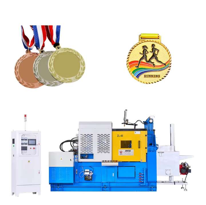
The Setup Phase Determines Everything
Walking up to a zinc die casting machine and expecting precision parts without a disciplined setup routine is like expecting a CNC machine to hold tolerances without indicating the vice. It doesn't work that way. The setup phase—from die mounting to parameter tuning to the first shot approval—sets the ceiling for what the machine can deliver over the entire production run.
Zinc offers inherent advantages for precision work. Its low melting point around 420–450°C means less thermal stress on dies and faster cycle times. Its excellent fluidity fills thin walls and complex geometries with minimal resistance. And its solidification shrinkage runs about 0.6%, which is low enough that dimensional stability comes relatively easily.
But those advantages only materialize if the machine is set up correctly. A sloppy setup turns zinc's strengths into weaknesses—poor die alignment causes flash, incorrect nozzle temperature leads to cold shuts, and improper shot parameters create porosity that defeats the purpose of choosing zinc in the first place.
Die Mounting and Alignment: Get This Wrong and Nothing Else Matters
Die mounting sounds simple: bolt the die halves to the stationary and moving platens, close the machine, and start casting. In practice, die alignment is where precision gets made or broken.
The first check is parallelism between the die faces. A gap of even 0.05 mm across the parting line means metal will flash out during injection, wasting material and creating safety hazards. More critically, misalignment stresses the die and the machine's toggle system, accelerating wear on both.
Dial indicators and laser alignment tools are standard equipment for a reason. The stationary platen and moving platen need to be parallel within 0.03 mm per 300 mm of platen width for precision zinc work. That's tighter than many shops realize—and it's worth checking not just during initial setup but after every die change.
Tie bar preload deserves attention too. Uneven tie bar stretching creates an unbalanced clamping force that can distort the die and produce parts with inconsistent dimensions. The standard practice is to measure tie bar elongation with a strain gauge and adjust the preload nuts until all four bars show within 5% of each other.
One precision zinc shop in Germany—they run connector housings for the automotive electronics market—learned this the hard way. They were holding ±0.03 mm on critical dimensions with a new die, but after three months, dimensions started drifting. The root cause turned out to be tie bar preload drift. Re-calibrating the tie bars brought the process back into control, but not before they scrapped two weeks' worth of production. The lesson: alignment isn't a set-once-and-forget task.
Nozzle Temperature and the Gooseneck: The Hot Zone
Zinc's low melting point makes hot-chamber machines the natural choice for most applications. The gooseneck and nozzle assembly sits immersed in the molten zinc bath, which keeps metal at temperature right up to the point of injection. But that same proximity to the melt creates temperature control challenges.
Nozzle temperature needs to be about 10–20°C above the molten bath temperature to prevent premature solidification at the nozzle tip. Too hot and the zinc oxidizes faster, creating dross that ends up in the casting. Too cold and the metal freezes in the nozzle, leading to short shots or cold shuts.
The gooseneck itself needs regular inspection for erosion. Zinc is less aggressive than aluminum, but over hundreds of thousands of cycles, the gooseneck bore still wears. A worn bore allows metal to bypass the plunger, reducing injection pressure and creating inconsistent shot weights. The telltale sign is a gradual increase in shot-to-shot weight variation. Replacing the gooseneck sleeve when wear exceeds 0.2 mm prevents this drift.
Thermocouple placement matters here. Measuring temperature at the bath isn't enough—the nozzle and gooseneck each need their own thermocouples, positioned close to the flow path. Smart operators also track the temperature profile during the first 10 shots after a setup change, because the thermal mass of a cold die draws heat away from the nozzle until everything stabilizes.
Injection Parameters for Sub-Millimeter Precision
The injection phase in zinc hot-chamber machines operates differently from aluminum cold-chamber systems. The plunger pushes metal up through the gooseneck and into the nozzle, then through the gate and into the cavity. Each stage needs its own parameter set.
First-stage (slow) shot speed moves the metal through the gooseneck without creating turbulence. For zinc, this typically runs 0.2–0.4 m/s. Too fast and air gets entrained; too slow and the metal cools before reaching the gate. The transition to second-stage (fast) shot happens when the metal reaches the gate—the exact point depends on shot sleeve and gooseneck geometry but is usually determined by plunger position.
Second-stage shot speed determines fill time. For precision zinc parts with wall thicknesses under 2 mm, fill times under 50 milliseconds are common. That requires gate velocities in the 40–60 m/s range. Reaching those speeds without creating mist or atomization demands a machine with responsive hydraulics and a well-tuned acceleration profile.
Intensification pressure in zinc is lower than in aluminum—typically 10–20 MPa—but it still matters for feeding shrinkage. Zinc's low shrinkage means the intensification phase is shorter, but eliminating it entirely invites porosity in thicker sections. The rule of thumb: apply intensification for 0.2–0.5 seconds after the cavity fills, then hold until the gate freezes.
A side-by-side comparison of zinc versus aluminum parameter ranges:
| Parameter | Zinc (Hot Chamber) | Aluminum (Cold Chamber) |
|---|---|---|
| Melt temperature | 420–450°C | 650–720°C |
| Slow shot speed | 0.2–0.4 m/s | 0.3–0.6 m/s |
| Fast shot speed | 2–4 m/s | 4–8 m/s |
| Gate velocity | 40–60 m/s | 30–50 m/s |
| Intensification pressure | 10–20 MPa | 80–120 MPa |
| Typical cycle time | 45–60 seconds | 60–90 seconds |
Cooling: The Dimension-Defining Variable
Cooling determines when the part can be ejected, but more importantly, it determines the final dimensions. Uneven cooling creates differential shrinkage, which pulls dimensions out of tolerance even if everything else is perfect.
Zinc's relatively high thermal conductivity—about 110 W/m·K compared to aluminum's 160 W/m·K—means heat transfers out of the casting quickly. That's good for cycle times but demanding on the cooling system. Water lines in the die need to be positioned to extract heat evenly across the part surface.
The critical rule: cool thick sections more aggressively than thin sections. Thick sections cool slower and shrink more, so they need more cooling capacity to match the solidification rate of thin sections. The alternative is a part that warps or develops internal stress that shows up as dimensional drift after ejection.
Temperature control units (TCUs) on each cooling circuit give operators the ability to fine-tune. A typical precision zinc die might have 6–12 independent cooling circuits, each with its own TCU. The setpoints vary by circuit—the gate area runs hotter to maintain fluidity, while the ejector side runs cooler to speed ejection. Stabilizing these temperatures within ±2°C eliminates a major source of dimensional variation.
A shop in Ohio producing zinc die-cast gears for power tools struggled with bore diameter drift from the start of a shift to the end. The bore was coming in at nominal in the morning but 0.02 mm undersized by afternoon. The culprit: the cooling water temperature in the plant was rising as the day warmed up, and the die's cooling circuits weren't compensated. Installing a chiller that held water at a constant 18°C eliminated the drift entirely.
Ejection and Lubrication: The Final Precision Gate
Part ejection seems routine until it isn't. A part that sticks in the die gets distorted during ejection, and that distortion becomes a permanent dimensional error. Ejector pin placement, ejection force, and timing all matter.
Ejector pins should be positioned to push evenly across the part surface. Uneven ejection stresses the part and can crack thin sections. The standard is to have at least four pins on any significant surface, positioned to balance the ejection load.
Lubricant application deserves more attention than it usually gets. In zinc die casting, the lubricant serves three purposes: it helps the part release from the die, it cools the die surface between shots, and it prevents soldering (zinc sticking to the die steel). Too much lubricant creates gas porosity and surface defects. Too little causes sticking and shortens die life.
The sweet spot varies by part geometry, but a good starting point is a spray pattern that deposits a thin, uniform film over the cavity surface—about 0.01–0.02 mm thick. Water-based lubricants dominate zinc work because they evaporate cleanly and don't leave residue that builds up over time. The spray time and volume should be tuned to the point where parts release cleanly without leaving a wet appearance.
One more thing: lubricant formulation matters. Zinc alloys are sensitive to certain additives. Some lubricants contain sulfur compounds that react with zinc at elevated temperatures, creating surface discoloration and, in extreme cases, intergranular corrosion. Sticking with well-known formulations from reputable suppliers and validating them with test shots before full production avoids this risk.
Process Monitoring and First Article Approval
No setup is complete without a disciplined first-article inspection. Running a few sample shots and checking dimensions on the bench isn't enough. The first article needs to represent the process at steady state—which means running enough warm-up shots to stabilize die temperature, nozzle temperature, and hydraulic oil temperature.
For precision zinc work, that warm-up period typically runs 20–50 shots, depending on part size and die mass. Measuring parts before thermal stabilization gives misleading data. The dimensions will shift as temperatures stabilize, and approving parts based on early shots guarantees trouble later.
Statistical process control (SPC) pays for itself quickly in precision zinc casting. Monitoring key dimensions on a regular interval—every 50 or 100 shots—catches drift before it produces scrap. The control limits should be set based on the process capability, not on the print tolerance. A process that's running at Cpk 1.5 needs different monitoring than one running at Cpk 0.8.
A disciplined setup routine that includes die alignment verification, nozzle temperature profiling, cooling circuit balancing, and first-article approval at thermal steady state isn't optional for precision work. It's the cost of entry. The shops that skip these steps spend their days fighting fires. The shops that do them systematically spend their days running parts that pass inspection.
Table of Contents
- The Setup Phase Determines Everything
- Die Mounting and Alignment: Get This Wrong and Nothing Else Matters
- Nozzle Temperature and the Gooseneck: The Hot Zone
- Injection Parameters for Sub-Millimeter Precision
- Cooling: The Dimension-Defining Variable
- Ejection and Lubrication: The Final Precision Gate
- Process Monitoring and First Article Approval